
Description
Name of File :- Moving Wheel Loads Analysis Design Excel Sheet

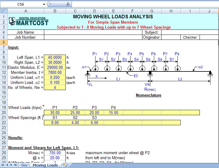
“MOVLOADS” is a spreadsheet program written in MS-Excel for the purpose of analysis of simple-span members subjected to from one (1) up to eight (8) moving wheel loads with up to seven (7) wheel spacing’s. Specifically, the maximum moment and location from the left end of the member and wheel positioning, the maximum end shears, the maximum deflection, and the maximum center support reaction for two (2) adjacent simple-span members are calculated.
This program is a workbook consisting of two (2) worksheets, described as follows:
- Worksheet Name
- Doc
- Moving LoadsProgram Assumptions and Limitations:
- The following references were used in the development of this program (see below):
a. “Modern Formulas for Statics and Dynamics, A Stress-and-Strain Approach” by Walter D. Pilkey and Pin Yu Chang, McGraw-Hill Book Company (1978), pages 11 to 21.
b. AISC 9th Edition Allowable Stress (ASD) Manual (1989), pages 2-298 and 2-310. - This program uses the three (3) following assumptions as a basis for analysis:
a. Beams must be of constant cross section (E and I are constant for entire span length).
b. Deflections must not significantly alter the geometry of the problem.
c. Stress must remain within the “elastic” region. - To determine the value of the maximum moment and location from the left end of the left span for either only one
(1) or two (2) wheel loads, those values are calculated directly by formulas. - To determine the value of the maximum moment and location from the left end of the left span for three (3) up to eight (8) wheel loads, the group of wheel loads is positioned with wheel load P1 situated directly over the left support. Then the group is moved to the right in 1/200*span increments, and the left and right reactions as well as the moments under each of the wheel loads are calculated. In moving the group of wheel loads incrementally from left to right, any wheels that would drop off of the span are done so. Then this entire procedure is mirrored for the opposite direction, from right to left.
- To determine the value of the maximum reaction at the center support of 2 adjacent simple spans, the group of wheels is positioned with the right most wheel load situated directly over the center support. Then the group is moved to the right, one wheel position at a time, until the left most wheel load, P1, is positioned directly over the center support. In moving the group of wheel loads one wheel position at a time from left to right, any wheels at either end that would drop off of the span(s) are done so.
- The calculated value for the maximum deflection is determined from dividing the beam into fifty (50) equal segments with fifty-one (51) points, and including all of the point load locations as well. (Note: the actual point of maximum deflection is where the slope = 0.)
- The user is given the ability to input two (2) specific locations from the left end of the beam to calculate the shear, moment, slope, and deflection.
- This program contains “comment boxes” which contain a wide variety of information including explanations of input or output items, equations used, data tables, etc. (Note: presence of a “comment box” is denoted by a “red triangle” in the upper right-hand corner of a cell. Merely move the mouse pointer to the desired cell to view the contents of that particular “comment box”.)
Formulas Used to Determine Shear, Moment, Slope, and Deflection in Single-Span Members
For Uniform Load:
Loading functions for uniform load evaluated at distance x = L from left end of beam:
FvL = -w*L
FmL = -w*L^2/2
FqL = -w*L^3/(6*E*I)
FDL = -w*L^4/(24*E*I)
Loading functions for uniform load evaluated at distance = x from left end of beam:
Fvx = -w*x
Fmx = -w*x^2/2
Fqx = -w*x^3/(6*E*I)
FDx = -w*x^4/(24*E*I)
For Point Loads:
Loading functions for each point load evaluated at distance x = L from left end of beam:
FvL = -P
FmL = -P*(L-a)
FqL = -P*(L-a)^2/(2*E*I)
FDL = P*(L-a)^3/(6*E*I)
Loading functions for each point load evaluated at distance = x from left end of beam:
If x > a:
Fvx = -P
Fmx = -P*(x-a)
Fqx = -P*(x-a)^2/(2*E*I)
FDx = P*(x-a)^3/(6*E*I)
Initial summation values at left end (xL = 0) for shear, moment, slope, and deflection:
Simple beam:
Vo = -1/L*S(FmL)
Mo = 0
qo = 1/L*S(FDL)+L/(6*E*I)*S(FmL)
Do = 0
Summations of shear, moment, slope, and deflection at distance = xL from left end of beam:
Shear: Vx = Vo+S(Fvx)
Moment: Mx = Mo+Vo*x+S(Fmx)
Slope: qx = qo+Mo*x/(E*I)+Vo*x^2/(2*E*I)+S(Fqx)
Deflection: Dx = -(Do-qo*x-Mo*x^2/(2*E*I)-Vo*x^3/(6*E*I)+S(FDx)
Reference:
“Modern Formulas for Statics and Dynamics, A Stress-and-Strain Approach”
by Walter D. Pilkey and Pin Yu Chang, McGraw-Hill Book Company (1978)


Reviews
There are no reviews yet